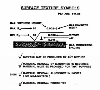
machining surface finish callout
Regardless both are applied after the mold cavities have been completely machined and their soon-to-be-textured surfaces smoothed to the requisite level. Two distinct processes are available but which one to use depends on the type of finish its surface depth and the mold material.

Surface Roughness Chart Understanding Surface Finishes Rapiddirect
But is that really true.
. So how far off can the center actually be. Many who are not familiar with GDT True Position may jump to the conclusion that they just need to locate within a thou and a half 00015 on X and Y and all will be well. Lets say the callout gives a true position tolerance of 00015.
For light texturing a corrosive chemical is applied in a controlled manner etching the mold. To understand the answer we must understand how to calculate.
Complete Surface Finish Chart Symbols Roughness Conversion Tables
Complete Surface Finish Chart Symbols Roughness Conversion Tables
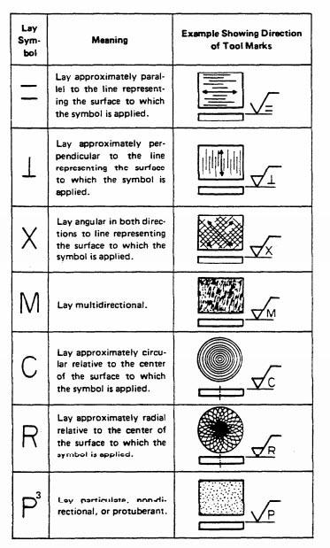
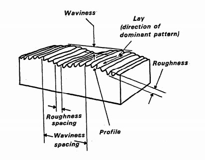
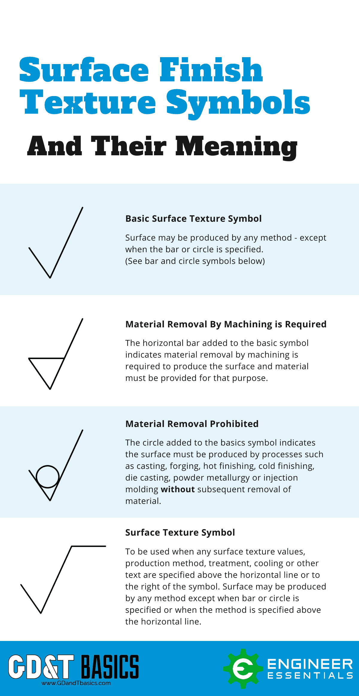
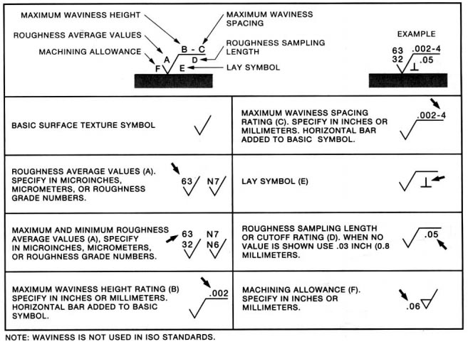
The Basics Of Surface Finish Gd T Basics
Why Use A Surface Finish Chart Metal Surface Finish
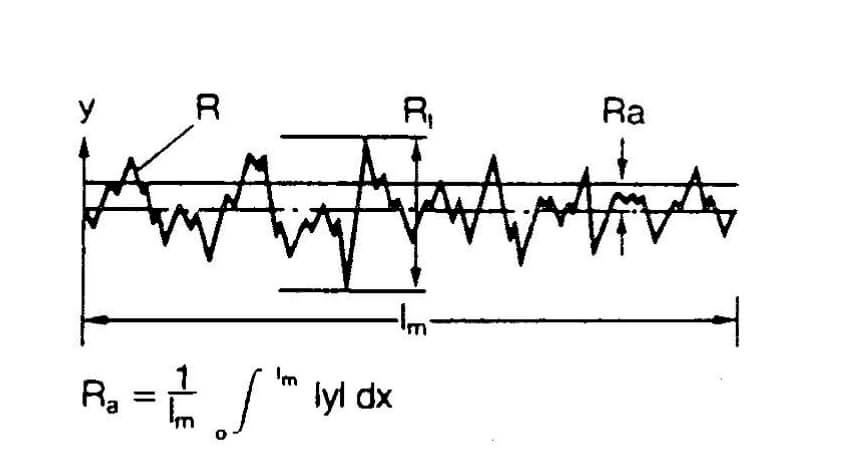
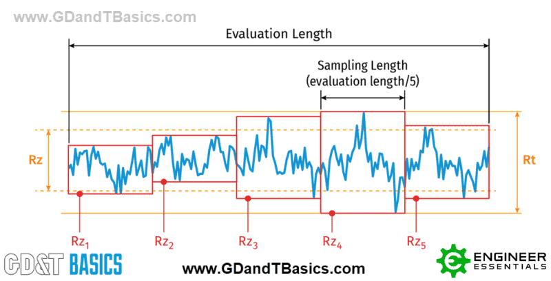
Surface Finish Quality Ra Rz Rt Surface Roughness Measuring Finish

Complete Surface Finish Chart Symbols Roughness Conversion Tables Surface Finish Symbols Surface Surface Roughness

Surface Roughness Indication To Iso Standard Autodesk Community
Complete Surface Finish Chart Symbols Roughness Conversion Tables
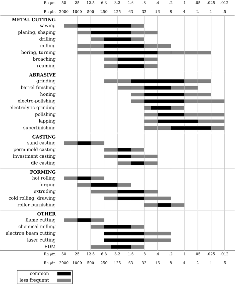
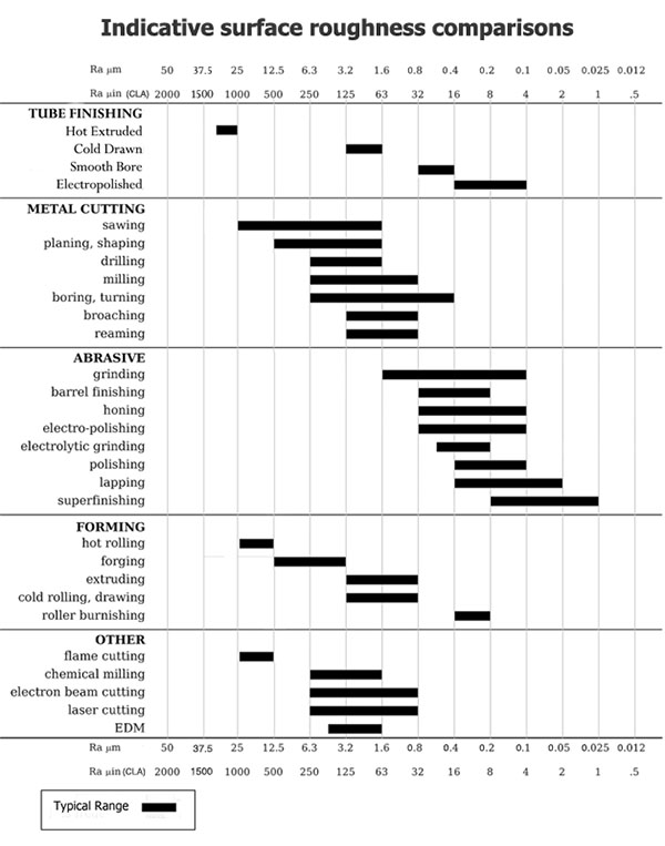
Machining Surface Finish Chart Conversion Comparator Method Degree Ra Rz Rms

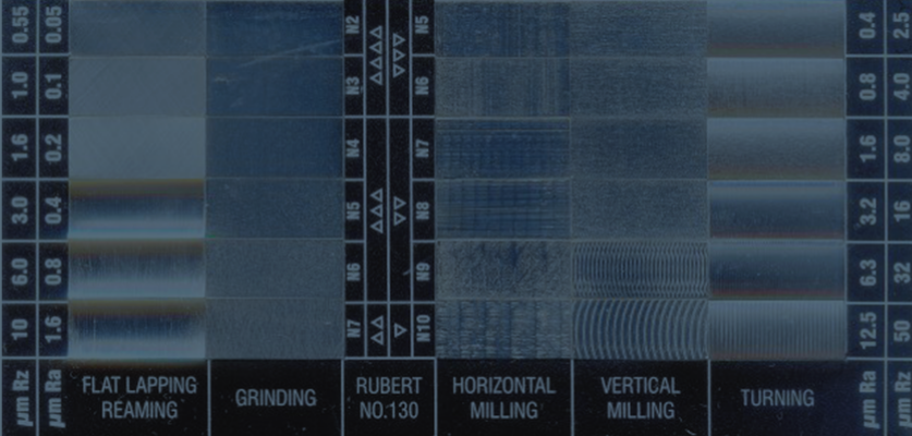
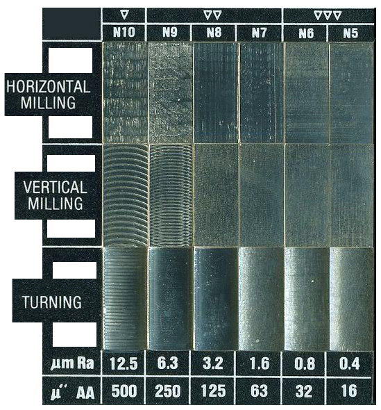
Surface Finish Destiny Tool

The Basics Of Surface Finish Gd T Basics
The Basics Of Surface Finish Gd T Basics
Complete Surface Finish Chart Symbols Roughness Conversion Tables

Surface Finish Destiny Tool
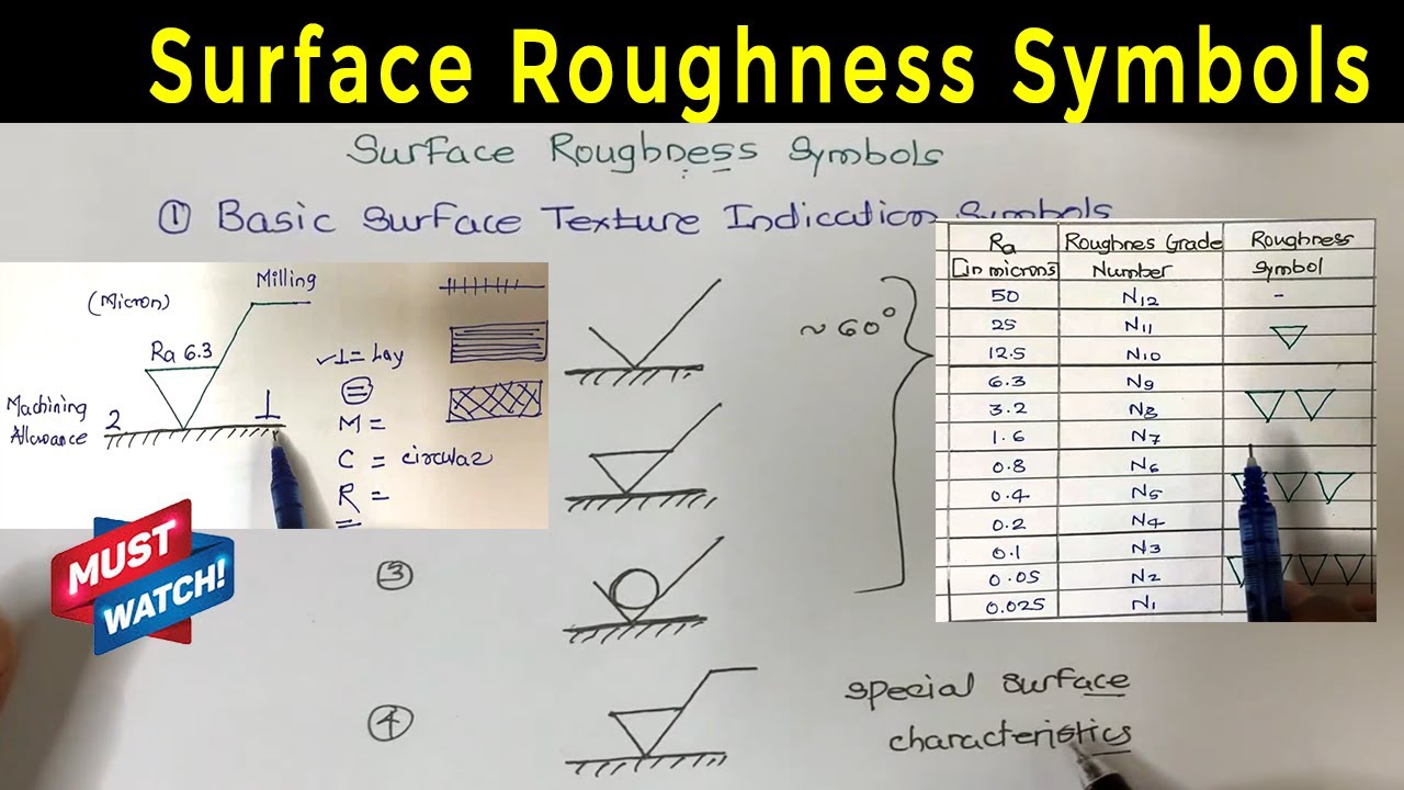
Surface Roughness Chart Understanding Surface Finishes Rapiddirect
The Basics Of Surface Finish Gd T Basics
Complete Surface Finish Chart Symbols Roughness Conversion Tables

Solved Iso Surface Roughness Symbol Missing Roughness Autodesk Community Fusion 360
The Only Surface Finishing Chart And Guide You Ll Ever Need